top of page

Building Upper Payload
The upper payload will consist of housing for the electronics and the CO2 charge assembly. Majority of the components will be made out of PLA and PETG plastic. The main mounting brackets for the wing will be made out of 5051 Aluminum sheet that will be bent to correct orientation. The constructions of the wings will be wrapped with a composite material around a very thin layer of 3D printed material. This 3D printed material will give the correct form and strength needed for the wings.
Drawing Tree
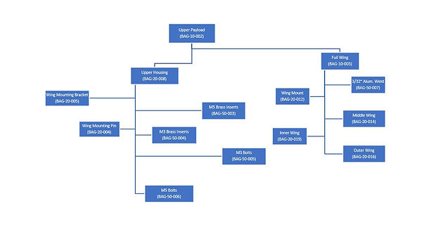
Figure 1- Upper Main Body

This is the upper main body of rocket, all the wing components as well as the electronics will be placed on the outside and inside of this body. The material is PETG with 25% infill. Three of the four mounting holes will have copper threaded inserts that are shown in picture. The other hole will be through with a bolt and nut holding component in place. The brackets attached to 3D printed part are 5051 Aluminum bent sheet metal and will be the mounting location for wings.
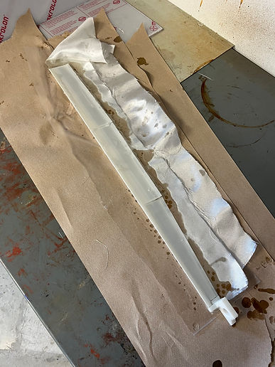
Figure 2- Wing Profile
This is the full wing wrapped with fiberglass. The fiberglass is a very tight weaved type of composite. It is infused with resin to give it a rock hard finish. This wing is made out of 3 separate 3D printed wing profiles, these wing profiles are hollowed out to reduce weight and print time. The overall weight of the wings are roughly 0.16 pounds.

Figure 3- Vacuum Bag Wings
This image is showing a wing in the vacuum bag with epoxy resin infused carbon fiber wrapped around it. The wing is laying on a negative that was 3D printed in 3 sections. Each section was printed with PLA at 5% infill and the reason for having negatives is so when the bags suction activates the carbon fiber follows a certain geometry. The vacuum bag takes all the air bubbles out of fiber and evenly spaces the epoxy resin so there is no weak points in overlay.
.jpg)
Figure 4- Carbon Fiber Preparation
Prepping carbon fiber for laying over a skeleton of wing or other geometry is a very tedious task. Unlike fiberglass the fibers do not stick together and can be unraveled quite easily. Using painters tape during prep helps keep the fibers together and while adding epoxy resin keep unwanted loose strands from getting in the way. Preparation is key when working with carbon fiber because any slight unravel to part can leave a weak point on final component. This can lead to premature failure and overall failure of payload.

Figure 5- Mounting Upper Body to Lower and Wings
This image is the key components of the entire payload minus the nose cone and a couple of the wings. These wings are some of the test wings which are wrapped in fiber glass. Components were designed with weight and size in mind. Every piece of payload had to fit within a 6 inch. cylinder and everything that is not within the nose cone had to fit in a 24 inch. long area of the cylinder. Manufacturing of components needed to be as perfect as possible to ensure clearances with in vehicle.

Figure 6- Video of Integration of Brass Inserts
This is a video showing how the brass threaded inserts are placed into a 3D print material. There are many ways this can be done and all are adequate. Since there are 40 inserts within this one component using a soldering iron to heat up insert which heats up surrounding PETG. This then causes the material to melt slightly and let the brass insert to be placed within wanted location. Once the material cools down the PETG adheres to the brass making a very strong bond.
bottom of page