top of page

Testing Payload
Testing is a crucial part of any engineering timeline of a project. Testing is extremely important especially when things can break without any warning. The more practice runs and fixing the better the project will run when it is released to public or expect to perform. This page shows the testing done on payload for strength tests and deflection tests of multiple components.
During the testing process there was a few issues that occurred but one main issue was during the wing deflection test. The wire system being used to place weight on wing kept sliding down when there was a great amount of deflection. Since the jig was adaptable to many different tests it was adapted to be able to pinch the wing so it could not move during testing.
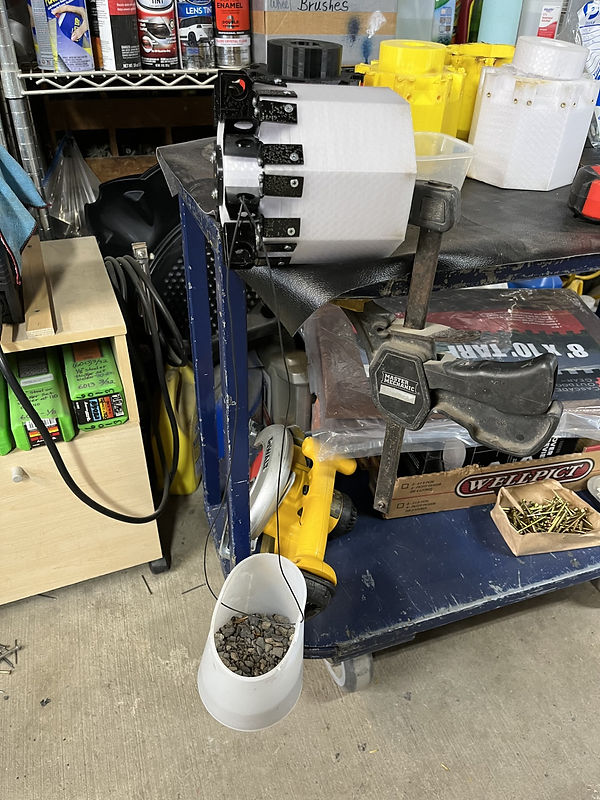
Figure 1- Aluminum Bracket Deflection Test
This test revolved around proving that the analysis of the Aluminum 5051 brackets meet the actual deflection given by a real piece of aluminum. The reason for doing it is to show that analysis is theory and in a perfect world, the world is not perfect and testing shows that the error between theory and real world needs to be small. The reason for doing this test with a very basic testing tool is so it can be done anywhere. These brackets need to have a certain amount of rigidity and strength which can be damaged due to material being too much deflection. It was found that the average deflection was roughly 1/32" and the target was 1/64" of deflection. It was found that the tolerance in testing due to measuring was around 1/64" which could be part of the problem with the recorded measurement. Also, the brackets have been flown and bent which also leads to issues with the material becoming weak. To fix this a couple things can be done, either using a not formed stock, a more precise way of measuring and/or a better way of clamping the test piece.
Figure 2- Testing Jig Weight
The image to the right is the bucket that was used for Test #1 and Test #2. The reason for using a very basic type of testing tool is because it can be used anywhere with any type of material. In this case gravel was used as the weight and measured to the specific weight needed to be tested. The holes in the top of the bucket are used to hold some kind of mounting equipment which in most cases a wire was used which can be seen in Figure 1.


Figure 3- Upper Body Deflection
This test was based on showing the strength of the Polyethelene Terephthalate Glycol (PETG) upper body of payload component. This component was used to house electronics as well as attached wings and CO2 charge to the entire payload. This part had to be not only a strong part but also a very resilient part. This test used the Instron to perform a loading test on part. The goal was to see that the body can withstand 105 pounds with no more then a 1/64" of deflection. The test was also designed to semi fail the part to show that even with a small fail the part will still perform adequately. It performed almost exactly as expected but with a little more deflection then initially wanted. This could have been from many complexities including over assumptions on analysis.
Figure 4- Wing Deflection Test
This test shown to the right was to test the deflection of the wing and its strength through loading. This wing chosen for testing the ultimately the wing with the least amount of strength compared to other due to carbon fiber and epoxy placement. The reason behind this is to test the weakest link and see where that would fail which in return would show the rest are stronger. Another reason for doing this was due to resources and time to make multiple extra wings to just be broken for testing. This test used a clamp to hold wing on a surface similar to that it would be in during flight. The jig that was used in Figure 1 and shown in Figure 2 was used to place weights on end of wing to perform a deflection. The wing is upside down because that is the orientation the load would be applied during flight. The wing was designed around 21 pounds of load applied on tip of wing with 1/64" of deflection.


Figure 5- Wing Failure
During the tests in Figure 4 it was done until failure. Failure was determined by when the wing can no longer return to its equilibrium after deflecting. This image shows the failure at 6 pounds of load placed at end of wing. The result can be explained by many causes the main one being the print infill of material. The analysis was based on a solid piece of material but the print was printed on 30% of infill to try to save weight for entire payload. Another major cause as well can be the stress concentrations not only on the outside geometry but also within the body of the mount. The grid type infill was used which has stress concentrates within the material in the corners and how the wing mounts to bracket also has stress concentrate. Since this design was tested it has been redesigned with more durable geometry.
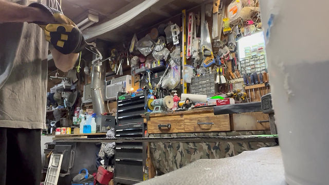
Figure 6- Video of Wing Deflection Test
This video shows how the deflection test was done and how the wing deflected with 2 pounds of load added to tip of wing.
bottom of page